ONIS
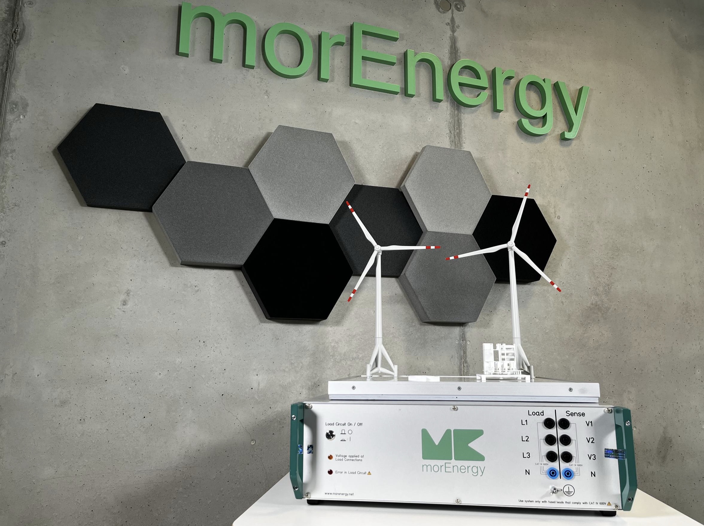
The Online Network Impedance Spectrometer ONIS can be used to perform high-frequency power quality measurements. Our specialty is network impedance measurement for the detection of dangerous resonances in the frequency range from DC to 500 kHz in the power grid. This solution sets us apart from the competition and allows us to detect problems before they arise.
Why ONIS?
Modern high-performance inverter systems can be found in fast-charging systems for electric cars, in high-rise elevators, on server farms and in both photovoltaic and wind power plants. They normally function reliably under the most difficult conditions. This highly efficient frequency inverter technology not only precisely controls the charging speed or the speed of elevators, but also ensures energy regulation on the power grid.
The reliability of the systems requires that the interactions between the frequency inverter and the power grid have been well assessed by the engineers when designing the controller. If this is not the case, e.g. due to complex power grids on site, it is not uncommon for instabilities to occur during operation, resulting in system failures.
With our ONIS technology, we prevent problems with the system integration of energy producers and consumers and proactively prevent system and revenue failures.
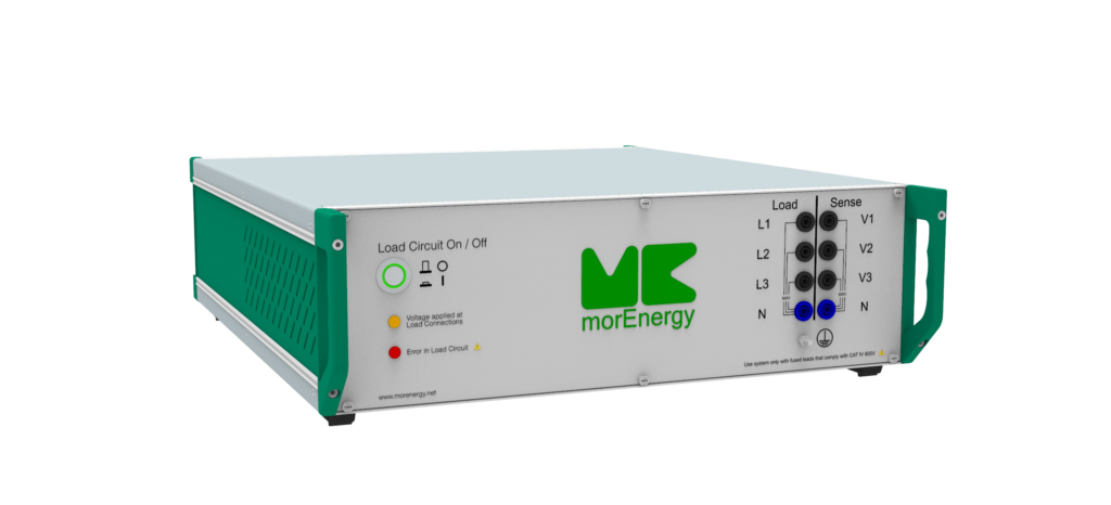
ONIS Models
The ONIS can be ordered in different versions, depending on the selection of voltage and maximum frequency. The table below shows the composition of the versions:
| Spannung / Max. Frequenz | 20 kHz | 150 kHz | 500 kHz |
| 600 Vpeak (400 Vrms) | ONIS 600 Classic | ONIS 600 Premium | ONIS 600 Plus |
| 1000 Vpeak (690 Vrms) | ONIS 1000 Classic | ONIS 1000 Premium | ONIS 1000 Plus |
PLC application
Power Line Communication (PLC) is used for smart metering systems and operates in the frequency range from 9 kHz to 487 kHz, in accordance with the CENELEC A, B, C, D, FCC and ARIB standards. This technology utilizes existing electrical infrastructure for the transmission of data. However, transmission interference can occur due to the specific properties of the cables. The causes of this include supraharmonic emissions, which amplify the background noise, and series resonances, for example due to LCL input filters from other devices, which create a low-impedance path for targeted emissions. In addition, the signal attenuation varies with the distance between the transmitter and receiver.
Power Quality application
The increase in decentralised energy generation and advanced electronic devices based on active power electronics leads to significant fluctuations in grid impedance at higher frequencies. These changes, caused by additional inductances and capacitances (such as LCL filters and DC systems), result in a large number of parallel and series resonances. This causes problems such as increased harmonic currents and voltages, overheating of the devices, noise generation, additional losses or the malfunctioning of devices and digital communication. Current grid codes (e.g. DACH-CZ, TOR, TAR) integrate resonance factors into the determination of emission limit values for harmonics, individually for each harmonic.
Control of supraharmonic emissions application
Supraharmonic emissions up to 500 kHz are becoming increasingly noticeable. These emissions are often caused by active power electronics, such as those used in photovoltaic systems, chargers for electric vehicles, wind turbines, heat pumps and similar technologies. Supraharmonic interference can affect the quality and stability of the power supply. It is therefore crucial to measure the grid impedance under different conditions in order to identify and resolve potential problems.
- Within a customer system: Here, measuring the grid impedance helps to understand the effects of supraharmonic emissions on the internal power grids. Especially in complex systems where numerous devices with active power electronics are operated, mutual interference often occurs. Early detection through impedance measurements makes it possible to take appropriate measures to ensure power quality.
- To the substation: In this case, measuring the grid impedance allows us to analyse how supraharmonic emissions propagate over longer distances in the power grid and what effects they have on the infrastructure and other consumers. Transmission over long distances in particular can lead to significant changes in impedance that affect the efficiency and reliability of the energy supply.
- Charging stations for electric vehicles: Charging stations are typical sources of supraharmonic emissions and even if they are not actively used, they can influence the local power grid. By measuring the grid impedance, potential disturbances can be identified and corrective measures initiated if necessary.
In all cases, measuring the grid impedance enables a precise diagnosis of the status of the power grid caused by supraharmonic emissions. This is a crucial step in ensuring high power quality and avoiding problems that can be caused by modern electronic devices and equipment.
Applications
PQ-Check: Checking the Power Quality
Get to the bottom of equipment failures or recurring defects.
Performance of grid interconnection points
Determination of the actual performance of grid connection points. Optimal allocation of resources for grid expansion.
Development of charging parks for e-mobility
Determination of dependencies and influences of different e-car models on each other.
Fingerprint of electrical system health
Focus on system health right from the start and create the basis for a long and efficient service life.
Additional Modules
Sub-Cycle Impedance Module
Determine the so-called sub-cycle impedance, i.e. the impedance of a certain period of the periodic sine wave of the mains voltage.
Battery supply module
With the help of the battery supply module, the mobility and flexibility of the ONIS measuring system is increased even further and the measuring system can be used more easily for long-term measurements, among other things.
Nominal mains frequency extension
In principle, nominal grid frequencies of the grid to be measured from DC to 800 Hz can be implemented.
Current and Power Module
Currents and power of systems are recorded and investigated. With this module, a more extensive recording of network points and plants is possible, as the current is also analysed at high frequency and a calculation of the complex, electrical powers is made possible. For the module, the ONIS measurement system is extended with three analogue inputs for current sensors.
PQ-Plus-Modul
With the additional module you get a more complete picture of harmonics at the mains connection. Not only symptoms, but also the cause of harmonics become more easily visible. All relevant characteristic values are calculated and displayed according to DIN EN 61000-4-7.